This video provides a brief overview of the WoodSolutions Mid-rise Demonstration Model. Building professionals are invited to tour the model in the company of a WoodSolutions representative, simply contact us at info@woodsolutions.com.au to find out more.
If you would like to visit the model contact us at: info@woodsolutions.com.au
STAGGERED STUD WALL (GROUND FLOOR)
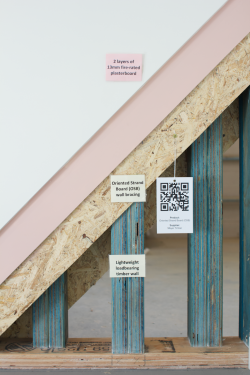
For the party walls at ground floor of a seven-storey timber structure, a “staggered stud” wall can be adopted, which is effective in reducing the transfer of vibrations from one side to the other. The example features double Laminated Veneer Lumber studs at relatively close centres, as specified to transfer significant loads. As this configuration doesn’t allow for the use of noggins, all studs are laterally restrained by bracing Oriented Strand Board sheets on each side.
The wall is lined with two layers of 13mm fire rated plaster board, tested to achieve a Fire Resistance Level of 90/90/90, a Deemed-To-Satisfy solution within the NCC.
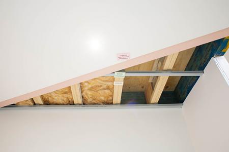
The ceiling demonstrates the required fire separation for a Deemed-To-Satisfy compliant floor between two sole occupancy units. While there are multiple ways to achieve compliance with these requirements, this system shows two layers of 16mm fire rated plasterboard that have been fixed to the bottom chord of the floor joists with acoustic isolation mounts. This configuration aids acoustic performance of the floor system whilst maintaining the minimum possible structural depth of the floor.
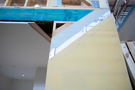
The outside of the non-loadbearing nib wall shows a façade system designed to deliver a render finish to framed structures. The façade panel has a pre-primed and textured base, ready for the addition of a textured acrylic coat. The system effectively acts as a pressure-equalised rainscreen, with a ventilated cavity between the visual façade and the vapour permeable membrane behind.
The vapour permeable membrane behind the rainscreen is non-combustible because, even though this wall is non-loadbearing, it is a requirement for all combustible elements utilised within a façade to be fire protected to a specified FRL. The system is completed by two layers of 13mm fire wet stop plasterboard.
HOLD-DOWN AND SHEAR BRACKETS
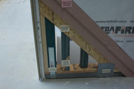
The outside face of the staggered stud wall shows different connectors typically used on walls located at the slab edge. The long hold-down on the left-hand side is designed to function in tension, and as such has been installed near the corner of the wall panel. In contrast to this, the shorter, wider steel plate on the right-hand side has been designed to function in shear and is therefore located closer to the centre of the panel. Note that each of these plates has been bolted to the grey concrete slab with a concrete anchor and has been connected to the timber element with nails.
CORNER DETAILS
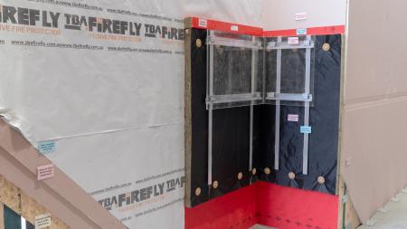
The internal corner demonstrates the use of external insulation behind a rainscreen cladding (here in clear Perspex, to see connections and bracketry behind it). In order of installation, this display demonstrates: fire protection, vapour permeable membrane, an intumescent cavity barrier, external insulation batts, an efficient rain screen façade bracketry system, the ventilated cavity, and finally the rain screen itself.
The external corner demonstrates a vertical connection between two CLT panels. Joints are sealed with a high-adherence non-permeable tape that limits air leakage into and out of the structure, to deliver the required air tightness. Note that this external corner also shows a typical angle connection between a massive timber panel and concrete slab.
OPERABLE SECTION
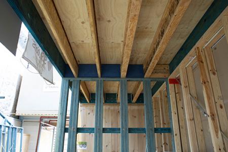
This section has been designed to be dis-assembled and re-assembled by project teams to better understand how panelised timber projects are put together. Optimised timber projects are typically made up of a variety of components, with safe and simple installation, as the floor element can sit under gravity loads while it is being fixed off, with no temporary propping required during install.
A great benefit of timber construction, all edge protection elements were pre-installed before lifting, eliminating all live edges on the project. This is a common experience on timber projects and is one of the reasons why timber construction is so safe.
DISCONTINUOUS WALL
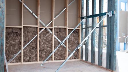
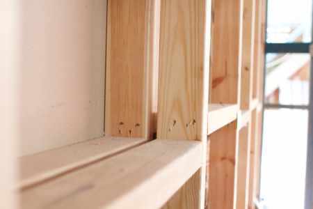
A high performing solution for multi-residential developments, a discontinuous wall features two frames which have been installed approximately 20mm apart, making them completely independent of each other. This complete separation eliminates the direct transfer of vibration from one wall panel to the other, and when combined with the two layers of fire rated plaster board required to reach a 90/90/90 FRL, achieves an acoustic rating higher than all other cost competitive wall types for a similar depth. Indeed, when completed, the system shown here has been proven to provide an Rw+Ctr or airborne acoustic rating of 54.
INTUMESCENT CAVITY BARRIER
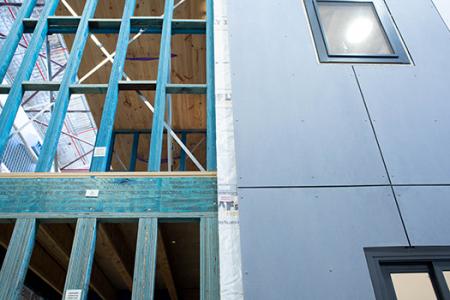
The floor level between the ground and first floors shows an example of an intumescent cavity barrier in its intended location. While only a few millimetres thick in its un-activated state, upon reaching a specified temperature this intumescent expands, filling the façade cavity with a non-combustible material and preventing the spread of flame under the cladding for a specified duration.
EXTERIOR WALL
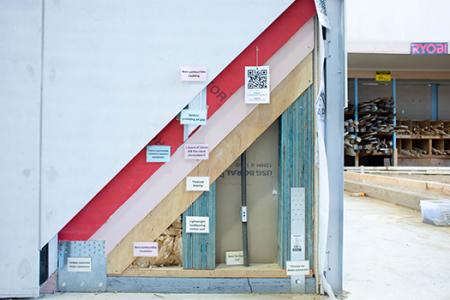
The right-hand half of this ground floor structural wall features a rain screen system supported by proprietary top hat sections. The structure is designed to transfer the loads of a seven-storey building, through triple LVL studs and a high strength F17 bottom plate. A continuous tie down rod is designed to resist the overturning forces applied by wind loads, with threaded rods coupled at each floor with turnbuckles, essentially delivering a single long steel cord to resist tension forces. This element is not required in all projects, by an engineer may elect to specify its use in particularly windy climates.
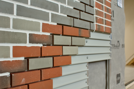
This section demonstrates a rainscreen façade system in the form of a lightweight brick finish, which can be applied on site, or prefabricated in a weather protected warehouse environment, then installed with joints “stitched” with the remaining bricks. While there are several prefabricated brick façade systems available for use with timber, the specific product seen here is structurally robust, and is suitable for use up to 30 storeys.
Immediately above this brick finish we can see a full fill solid timber cavity barrier. Note that this would normally be covered by the façade cladding, but we have chosen to reveal it here for display purposes only. Above the cavity barrier, the details of the external side of a solid balustrade are shown (and fully visible from Level 1).
INTERIOR FINISHES
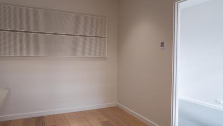
This room has been finished to the standard one may expect in a completed project – the only un-finished work here is in the power point which has purposefully been left out to show the fire box behind it – a requirement when penetrating a fire rated element.
CORE OPTIONS
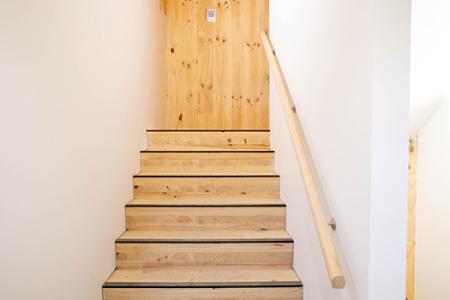
The structural core has been designed as a stair shaft but could be a lift core or services rise as need be. Finishes are purposefully kept to a minimum to show all of the connections between the elements. The Cross Laminated Timber elements illustrated in this section are perfectly cut to size and held together with high capacity screws and connectors. The stair flights are also completely pre-fabricated.
At a higher level within the Demo Building, the Laminated Veneer Lumber option is also shown. Structural cores have also been designed with stud frames in some mid-rise projects.
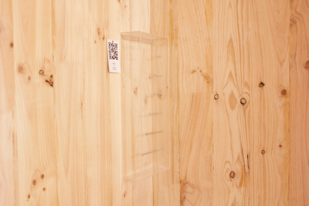
A small display of screws typically used to connect massive timber structures. Certain screws are able to perform the same function as an angle bracket, minimising the visual impact of the connection. A key feature of engineered timber products, lamination reduces the impact of knots and other natural features of the tree by staggering them across a given section, delivering a whole that is stronger and more robust than the sum of its parts.
SERVICES INSTALLATION
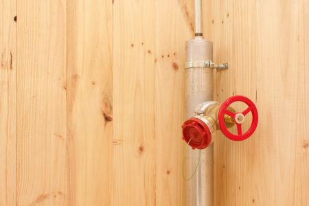
A mock-up fire hydrant riser demonstrates the basic connection detail between services and timber eements. All services can be roughed in and connected to the structure with the use of nothing more than screws and a battery powered screwdriver.
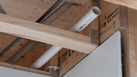
WALL TRUSS BRACE
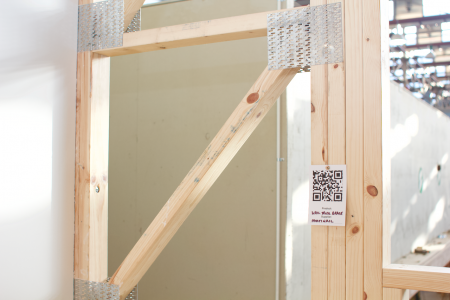
Walls with a large window opening would typically require heavy ply bracing to provide resistance to lateral forces. A good alternative can be wall truss brace, essentially a vertical truss providing increased stiffness to the opening.
FIRE RATED PENETRATIONS
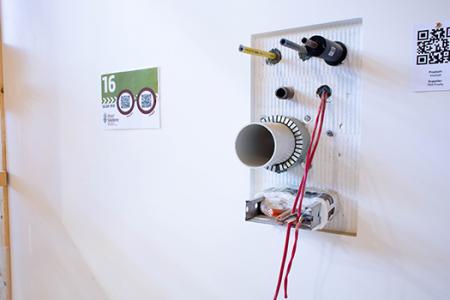
It is very important to correctly design and execute penetrations through fire-rated walls. A multi-service penetration is sometimes an optimised solution. To ensure compliance it is important to ensure that all timber structure on both faces, and inside the penetration are lined to achieve the desired FRL. The void can be filled with high-density non-combustible insulation, with all service penetrations running through. Note the different fire stopping requirements of different services.
BATHROOM FLOOR SETDOWNS
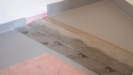
A bathroom floor set down can simply be fabricated into the floor panels or cassettes. Here the watertightness is achieved with a traditional cement sand screed system and a liquid waterproofing membrane, and two options are shown for the service risers.
FLOOR ACOUSTIC BUILDUPS
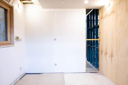
This room illustrates two different acoustic build-ups suitable for a typical multi-residential project. The acoustic performance of a floor system is largely determined by its mass and its ability to dampen impacts to minimise the transfer of vibration.
There are a wide variety of acoustic build ups that can be used, and we do provide advice through calculated comparisons. While a concrete screed has been used in the past, builders are now often preferring to utilise dry alternatives such as demonstrated here.
Notice that both acoustic systems shown feature a foam strip where the floor build-up meets the wall, to minimise the transfer of impact noise from the floor system to the wall, effectively reducing structural borne, or “flanking” noise.
ACOUSTIC CEILING
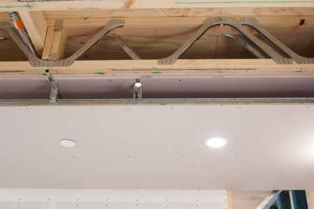
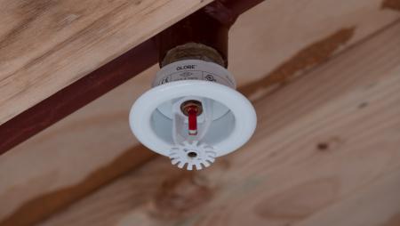
When the floor structure is made of lightweight joists, the ceiling system can have the fire rated linings applied direct fix to the underside of the floor joists, with a cavity and dropped ceiling below, for the easy reticulation of services without penetrating the fire lining. An effective alternative to the ceiling system shown on the ground floor, this system typically requires larger floor depths to achieve the same acoustic performance, however may allow for the pre-installation of fire rated linings before the cassette is delivered to site, greatly reducing plastering labour required on site. And, with minimal penetrations to the fire rated lining, this system does not require the use of fire rated downlights or sprinkler fire-boxes.
BALCONY
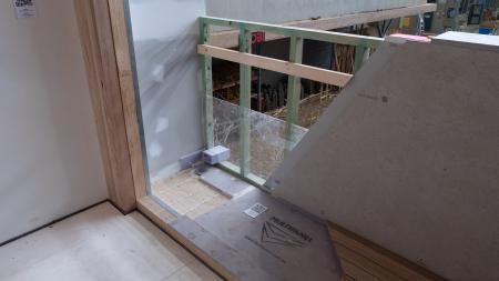
While we typically recommend the use of “bolt on” balconies whose structure is completely separate to that of the main building, it is common for balconies to cover a habitable space. This balcony details demonstrate this scenario and assumes that the balcony surface cannot be set down from the other areas.
To achieve this height separation, a 90mm high hob is made with two treated pine studs. Then a proprietary waterproofing system is used, that can be machined to include a fall, where individual components are glued together with a polyurethane compound, providing a completely watertight membrane.
Balustrades vary substantially in material and design, however in this display we have shown how you can build a solid balustrade as is common in in-set balconies. This element is fully exposed to the weather, and as such requires a similar treatment to the façades seen at ground floor.
STAIR CORE
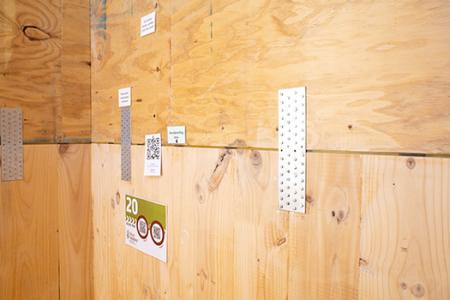
This detail shows the transition of the core structure from CLT to LVL, to illustrate both materials and the possibility to combine them.
At this horizontal joint between the two massive timber elements, a thin yellow rubber strip is installed to limit the transfer of vibration between panels. A great benefit of panelised construction over monolithic structures, the accurate use of these strips can minimise the transfer of structure borne sound, improving internal environmental quality throughout a structure.
Also visible are timber to timber plate connectors, designed to transfer tensile loads.
STAGGERED STUD WALL
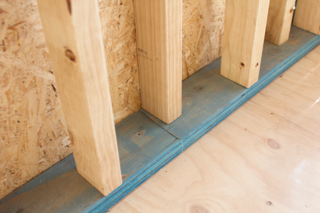
The top floor of the model represents what could be the top three storeys of a building, where the structure is subject to significantly reduced loads. Comparing this MGP10 staggered stud wall to its equivalent on the ground floor, which featured double LVL studs staggered at 150mm centres – a significant difference illustrates how design can be optimised.
LIFTING AND FALL PROTECTION
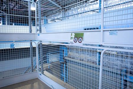
In the demountable part of the building, a CLT panel (and a light frame cassette floor at the lower level) allow to practice the installation sequence and speed, including that of the robust fall protection, and experience the under-foot feel. Note that both lightweight and massive systems are completely bare, with no fire rating underneath, and no acoustic build up on top.
ROOF
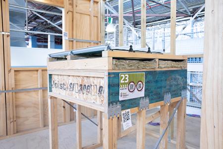
While traditional on-site roofing is still common, it is also possible to build roof cassettes, significantly reducing the amount of work to be completed on site. The example here shows a flat cassette which features battens, external insulation, deep profile roof cladding, and a fall restraint anchor. Where the element is prefabricated complete with cladding, some cladding would typically be left off on either edge of the cassette so it may be “stitched” together and made watertight once installed.
